Standard Features:
Front railsweeps and hydraulic activation are standard. Components include an electrically driven hydraulic power unit, valves, hydraulic cylinders, hoses and fittings.
Optional Features:
Railwheel brakes, wide and narrow gauges are available as options.
Materials:
All structural members and brackets are constructed of carbon steel. The 10″ guidewheels for DMF RW-1019 railgear are machined from hardened steel castings and are fitted to high strength alloy steel axles with heavy-duty tapered roller bearings.
Installation:
Both DMF front and rear guidewheel units bolt to the truck frame using only hand tools found in any shop. They are designed to minimize the amount of space required and in many cases fit within the existing boundaries of the vehicle. The front units, however, sometimes require a bolt-on frame extension to complete the installation. Rear RW-1019 railgear mounts below the top of frame and directly behind the chassis spring hangers. This minimizes intrusion into truck body installations. Please note that center-mounted fuel tanks behind the rear truck axle are not desirable. If possible, opt for the mid-mounted tanks.
Brakes:
RW-1019 rail brakes are hydraulically actuated external shoes. The hydraulic power unit that raises and lowers the railgear also operates the brakes. When the dashboard mounted enable switch is turned on, the brake lamp signal is used as a trigger to run the pump and divert hydraulic pressure to the brakes. A built in safety circuit protects the truck’s brake lamp system as well as the hydraulic power unit from excessive run times.
Operation:
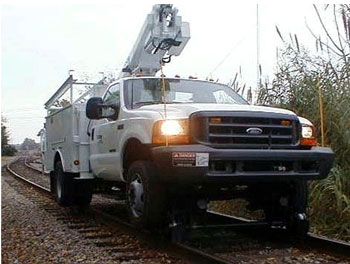
The truck is pulled onto a crossing and the wheels aligned to the tracks with attention being paid to the front. The operator then activates the hydraulic power unit by pressing the button on the front bumper and pulling the lever of the hydraulic valve to raise the railgear off of the pin-off device. The safety pins are removed and the lever pushed forward lowering the rail wheels to the track. The front gear will lift the front of the truck and go over center. The rear is operated similarly. The gear is raised to lift the weight from the pin-offs, and the pins are removed. The gear is then lowered via the two handled valve at the rear of the truck. Each spool may be operated independently to articulate the rear gear and engage the rail even if the rear wheels are not perfectly aligned. Once the rear gear is fully deployed, the pin offs are re-inserted to lock the gear in place.
Steering Wheel Lock:
A steering wheel lock is provided, requiring no modifications to the column.
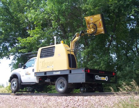
 DMF’s RW-1019 railgear is a scaled down version of our patented and very successful RW-1630 gear for large trucks. The front guidewheel assembly attaches to the frame and front axle and lifts the front wheels off the track, thus utilizing the vehicle’s front suspension. This design supports the vehicle as it was intended and helps the truck navigate curves smoothly and damp out the effects of track irregularities. The rear assembly attaches directly to the truck frame behind the rear axle spring hanger. It deploys with an articulated dual scissor action that allows the rear railgear to be moved both vertically and horizontally. This mechanism provides the “side shift” action which has made DMF gear so well-known in the industry. It gives operators a greater margin for aligning the vehicle to the track which speeds and simplifies the process of getting the vehicle on rail.